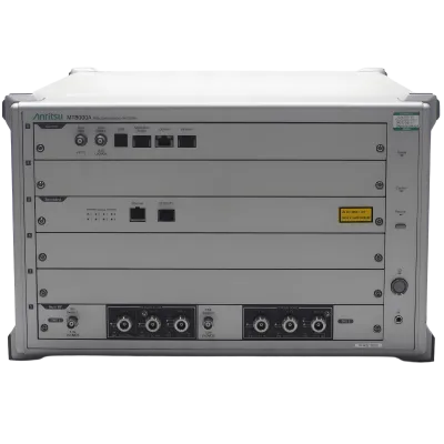


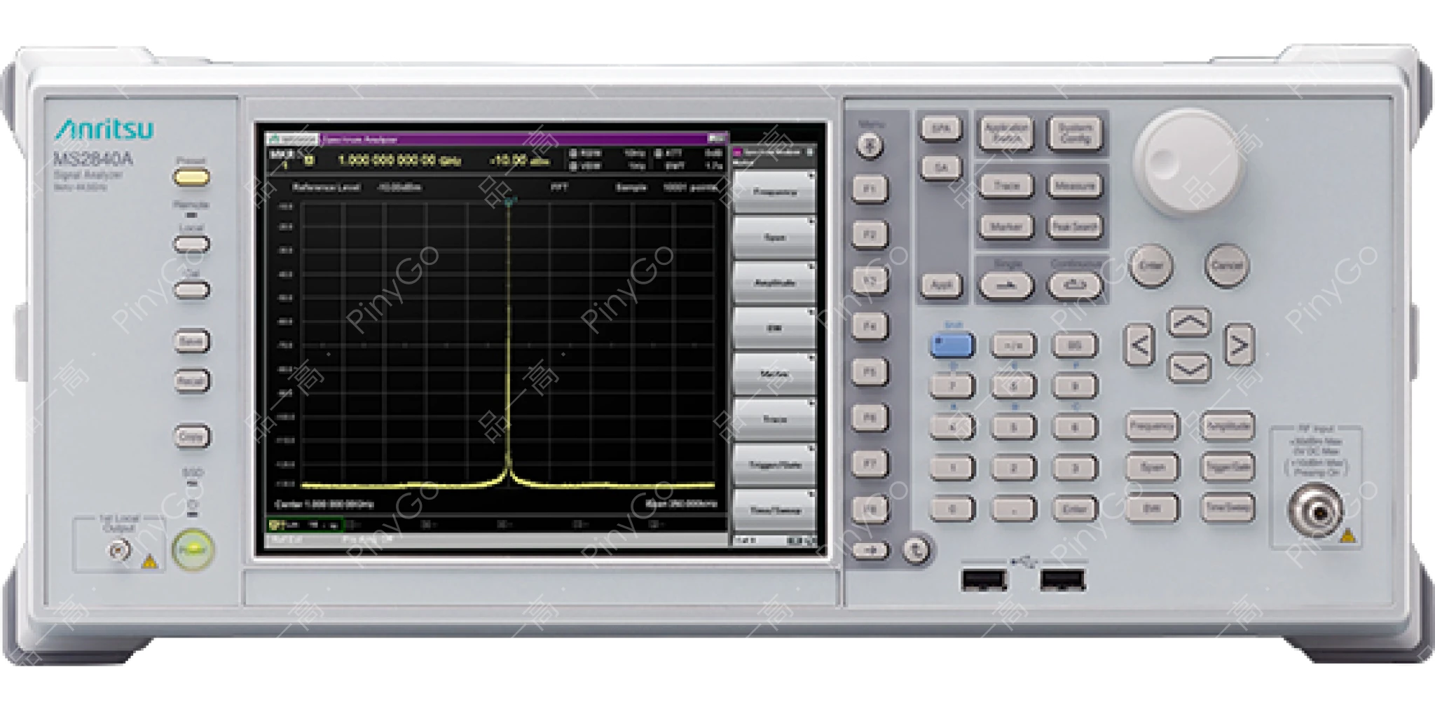
Spectrum Analyzer/Signal Analyzer MS2840A
Manufacturers
Anritsu
Other Recommendations

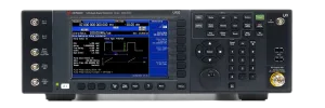
High-Performance Spectrum/Signal Analyzer, 9kHz-44.5GHz Frequency Coverage with Exceptional Phase Noise Performance
📡44.5GHz
9kHz-44.5GHz full-band coverage for microwave/mmWave testing (Frequency parameter)
📉-140dBc/Hz
-123dBc/Hz@1GHz/10kHz offset (Option: -140dBc/Hz) for precise near-carrier spurious measurement (Key feature)
📶125MHz Bandwidth
Standard 31.25MHz, optional 125MHz analysis bandwidth for real-time wideband signal processing (Key parameter)
| Core Parameter | Detailed Specifications | Application Value |
|---|---|---|
| Frequency & Phase Noise | 9kHz-44.5GHz, SSB phase noise -123dBc/Hz (1GHz,10kHz offset), option down to -140dBc/Hz | Measures near-carrier spurious in microwave backhaul transmitters (e.g., ≤-80dBc@10kHz offset), ensuring carrier purity |
| Analysis Bandwidth & Functions | Standard 31.25MHz, optional 125MHz; 3.6/6GHz models feature built-in signal generator for closed-loop testing | Real-time analysis of 5G NR 100MHz bandwidth signals. Single-unit completes "stimulus-response" tests (e.g., power amplifier linearity) |
| Measurement Applications | Optional phase noise, noise figure, vector/analog modulation analysis, BER, pulse radar measurement | Tests FM modulation accuracy in PMR equipment (deviation error ≤2%), pulse width in mmWave radar (±0.1μs), covering multi-scenario needs |
Core Application Scenarios
Microwave Backhaul Equipment Testing — Utilizes -123dBc/Hz phase noise to measure 10kHz offset spurious in 28GHz backhaul transmitters (Requirement ≤-85dBc). Ensures adjacent channel interference suppression (Measured -88dBc → Pass)
VHF/UHF PMR Device Verification — 125MHz bandwidth analyzes VHF band (136-174MHz) trunking signals. Tests FM modulation stability (±1kHz deviation) and THD (≤3%)
5G mmWave Component Testing — 44.5GHz model measures mmWave power amplifier output spectrum (e.g., spurious ≤-60dBc in 39GHz/100MHz bandwidth), noise figure testing (Requirement ≤8dB)
Scenario Deep Dive
Core Technical Architecture
Features "Low Phase Noise RF Frontend + Wideband Real-Time Analysis + Modular Expansion" design:
1. RF Frontend: Tiered coverage 9kHz-44.5GHz. Low-noise PLL achieves -123dBc/Hz@1GHz phase noise. Built-in preamp (44.5GHz model) improves sensitivity (≤-150dBm)
2. Signal Processing: 12-bit ADC (≥500MSa/s sampling) supports 125MHz analysis bandwidth. FPGA calculates phase noise and EVM in real-time (Latency ≤200ms)
3. Functional Expansion: Optional phase noise test package (0.1Hz resolution), 5G NR modulation software. 3.6/6GHz models integrate signal generator (20MHz vector modulation) for closed-loop testing
| Technical Dimension | MS2840A | MS2830A (Same Series) | Advantage Demonstration |
|---|---|---|---|
| Phase Noise Performance | -123dBc/Hz (1GHz,10kHz offset), option down to -140dBc/Hz | Typical -110dBc/Hz (1GHz,10kHz offset) | In microwave backhaul testing, near-carrier spurious measurement resolution improves by 13dB. Detects weak spurious at -90dBc (undetectable by MS2830A). R&D efficiency increases 50% |
| Analysis Bandwidth & Speed | Optional 125MHz, 100MHz signal analysis time ≤200ms | Max 62.5MHz, same signal analysis time ≥500ms | In 5G NR wideband testing, production sampling efficiency increases 2.5x. Daily test capacity rises from 300 to 750 units per device |
Microwave Backhaul Transmitter Phase Noise Test Workflow (28GHz Band)
Connection: MS2840A (44.5GHz model) connects to transmitter output via 28GHz low-loss cable. Enable phase noise option. LAN port connects to control PC (configures test parameters)
Configuration:
- Frequency & Offset: Center frequency 28GHz, offset range 100Hz-1MHz (Focus on 10kHz-100kHz near-carrier region)
- Measurements: Phase noise (Requirement ≤-100dBc/Hz@10kHz offset), spurious level (≤-85dBc@10kHz offset)
- Calibration: Perform system calibration (including cable loss compensation, ~2dB/m loss at 28GHz)Test Execution:
- Signal analysis: Device automatically scans offset frequencies. Measures -105dBc/Hz phase noise@10kHz (Pass), but detects -78dBc spurious@15kHz offset (Fail)
- Root cause: Spectrum analysis confirms spurious from transmitter LO leakage (28GHz±15kHz), correlated with power supply ripple (15kHz)Optimization Verification: Add 15kHz notch filter to LO power supply. Retest shows spurious reduced to -87dBc (Pass), phase noise unchanged (-104dBc/Hz), confirming optimization effectiveness
Usage Precautions
1. Full calibration (reference source, cable loss, temperature compensation) is mandatory before phase noise testing. Otherwise, measurement error may exceed 5dB@10kHz offset, causing misjudgment
2. For 44.5GHz band testing, use specified mmWave cables (e.g., WR-28 waveguide-to-coax) and compensate insertion loss in software (calibrate when loss ≥2dB/m) to avoid power measurement deviation
3. Balance speed vs. accuracy when using 125MHz bandwidth: Wider bandwidth enables faster capture (200ms) but increases RBW (minimum 1kHz). For high-precision measurements, use 31.25MHz bandwidth (100Hz RBW)