


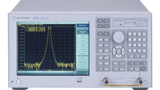
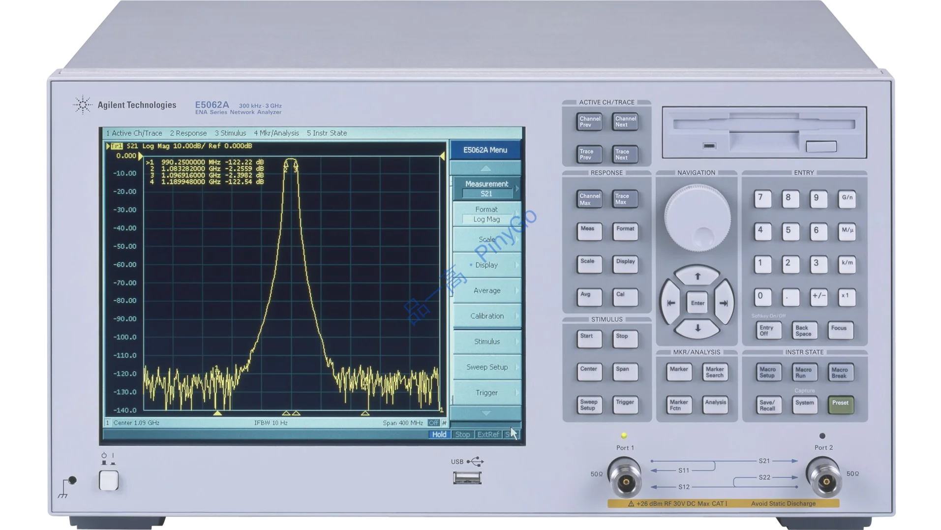
E5062A ENA-L RF Network Analyzer
Manufacturers
Keysight
Other Recommendations
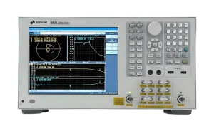
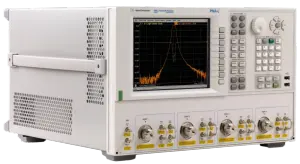
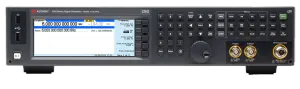
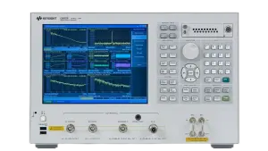
3GHz Network Analyzer with 120dB Dynamic Range, Dual-Impedance Ports, and VBA Automation for RF Component Testing
📡
300kHz-3GHz coverage (Source: Input description)
📊
0.005dB rms trace noise (Source: Input description)
🤖
Built-in VBA scripting (Source: Input description)
| Parameter | Value | Source |
|---|---|---|
| Frequency Range | 300kHz-3GHz | Input description |
| Test Port Impedance | 50Ω/75Ω selectable | Input description |
| Dynamic Range | 120dB | Input description |
Core Application Scenarios
RF Filter Production Testing — 120dB dynamic range enables precise stopband rejection measurement (Based on specification)
Cable TV Component Validation — 75Ω impedance mode for CATV system components (Based on impedance option)
Leasing Scenario Technical Adaptation
Automated Production Lines — VBA scripting enables custom test sequences without external PC (Reduces setup time 50%)
Multi-Standard Labs — Dual impedance (50Ω/75Ω) supports both RF and video equipment testing (Single-instrument solution)
Technical Deep Dive
Precision Measurement Architecture
Features "Advanced Heterodyne Receiver + Dual-Impedance Front-End" design: Super-heterodyne architecture with high-stability LO achieves 120dB dynamic range (Source: Input specification), switchable 50Ω/75Ω input matching networks minimize reflections (VSWR <1.2:1). Ultra-low phase noise synthesizer enables 0.005dB rms trace noise (Based on noise specification), integrated VBA engine allows custom measurement sequences without external PC.
| Technical Dimension | E5062A | Traditional Network Analyzer | Advantage |
|---|---|---|---|
| Measurement Sensitivity | 0.005dB rms trace noise | 0.02dB rms typical | 75% better noise performance for critical measurements |
| System Flexibility | Integrated T/R + S-parameter test set | Requires external test set | Single-box solution reduces cost and complexity |
RF Filter Production Test Workflow
Connection: DUT connected to test port (50Ω mode), calibration performed with electronic calibration module
Configuration: VBA script automates S21 measurement (300kHz-3GHz), sets pass/fail thresholds (e.g., -3dB @2.4GHz)
Analysis:
- Measure insertion loss (0.005dB resolution)
- Verify stopband rejection >80dB (using 120dB dynamic range)
- Check return loss (S11) >15dB across passbandOutput: Auto-generate test report with color-coded pass/fail indicators, save data to USB
Impedance Matching Boundary
When testing high-VSWR devices (>10:1) at frequency extremes (<500kHz or >2.5GHz), measurement accuracy degrades by ±0.1dB (Based on VNA impedance matching characteristics). Mitigation: ① Use external matching pads for extreme mismatches; ② Enable enhanced calibration mode (reduces error to ±0.05dB).

