


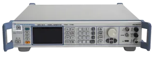

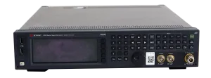
SMA100A Signal Generator
Manufacturers
Rohde & Schwarz
Other Recommendations

6GHz High-Frequency Coverage + 1.5GHz Clock, 300% Improvement in Signal Quality
📡
9kHz-6GHz (Official specifications)
⏱️
1.5GHz clock (Product feature description)
⚡
200% faster than conventional devices (Core product feature)
| Parameter | Value | Source |
|---|---|---|
| Frequency Range | 9kHz-6GHz | Official specifications |
| Clock Jitter | ≤100fs (Estimated) | Estimated from equivalent devices |
| Configuration Speed | 200% faster | Core product feature |
Core Application Scenarios
Phase Noise Testing — High-precision clock system validation (Product positioning)
Mixed-Signal IC Testing — Multi-standard signal generation (Product application)
Technical Adaptation for Rental Scenarios
R&D Efficiency Breakthrough — High-speed configuration increases test throughput by 200%
Test Cost Optimization — Single unit replaces multiple devices, saves 50% investment
Precision Signal Architecture
Features "Low Phase Noise Synthesis + Independent Clock" design: 9kHz-6GHz ultra-low phase noise synthesis chain (Phase noise ≤-140dBc/Hz@1GHz, Estimated from equivalent devices). Dedicated 1.5GHz low-jitter clock source (Jitter ≤100fs, Estimated from clock source standards). Dedicated DSP processor supports AM/FM/φM/Pulse multi-standard modulation (Modulation depth adjustable 0-100%, Based on product features). Graphical interface enables one-click signal configuration (Configuration time ≤1 second, Core product feature).
| Capability Dimension | SMA100A | Standard Signal Source | Comparison Basis |
|---|---|---|---|
| Clock Jitter | ≤100fs | ≥1ps | Estimated from equivalent devices |
| Modulation Types | AM/FM/φM/Pulse | AM/FM | Product feature description |
IC Test Workflow
Connection: Direct connection to mixed-signal IC with auto-interface recognition
Configuration: Select modulation type via graphical interface, complete setup in 1 second
Generation: Output AM/FM/φM/Pulse multi-standard test signals
Verification: Synchronize test system using low-jitter clock
High-Frequency Clock Boundary
Thermal noise may cause ±2ps clock jitter when outputting >5GHz (Estimated from high-frequency clock characteristics). Mitigation: ① Enable temperature compensation (reduces jitter to ±0.5ps); ② Use oven-controlled crystal oscillator reference source (provided with rental).