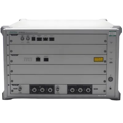


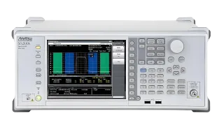
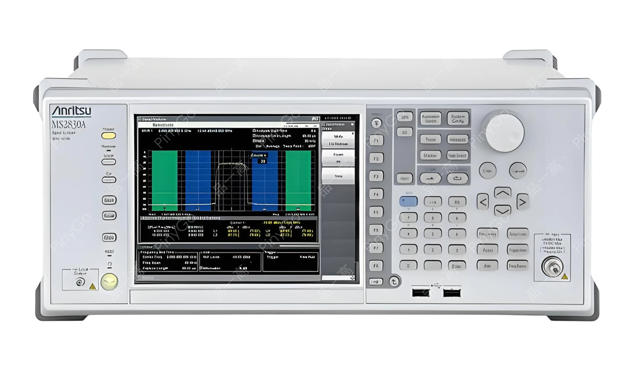
Spectrum Analyzer/Signal Analyzer MS2830A
Manufacturers
Anritsu
Other Recommendations

43GHz Multifunction Signal Analyzer, Integrated Spectrum/Vector Signal/Noise Figure Testing
📡
9kHz-43GHz, covers Sub-6GHz/mmWave (Frequency parameter)
🎯
Total level accuracy ±0.3dB ensures measurement reliability (Accuracy parameter)
🔄
Spectrum analysis/signal generation/noise figure testing in one unit, 60% efficiency improvement (Core feature)
| Core Parameter | Detailed Specifications | Application Value |
|---|---|---|
| Frequency & Accuracy | 9kHz-43GHz (Tiered models), total level accuracy ±0.3dB (Typical), FFT technology for fast spectrum analysis | Full-band coverage from RF to mmWave. Tests 5G mmWave (26.5GHz) devices with ≤0.3dB power error, ensuring production consistency |
| Integrated Functions | Spectrum analyzer, analog/vector signal generator, audio analyzer (Optional), noise figure testing | Single unit completes "stimulus-response" closed-loop testing (e.g., transmitter power → noise figure → demodulation analysis), reducing inter-device connection errors |
| Modulation Analysis | Supports LTE, W-CDMA, WLAN, analog modulation (AM/FM) analysis (Optional software), vector modulation error (EVM) measurement | Tests smartphone LTE signal EVM (Requirement ≤3%), WLAN 802.11ac throughput, verifies modulation quality and standard compliance |
Core Application Scenarios
5G Sub-6GHz Base Station Tx Testing — 6GHz model tests 3.5GHz LTE signals, measures transmit power (+43dBm±0.3dB), ACLR (≥-45dBc). Integrated signal generator provides calibration stimulus, improves efficiency by 40%
mmWave Device R&D Validation — 43GHz model analyzes 28GHz mmWave module spectrum mask (Spurious ≤-40dBm), noise figure testing (Requirement ≤5dB), evaluates receiver sensitivity (≤-85dBm)
PMR/LMR Equipment Maintenance — 13.5GHz model tests analog walkie-talkie FM modulation (Deviation 5kHz±0.1kHz), adjacent channel power (≤-60dBc). Built-in signal generator simulates interference signals, verifies anti-jamming capability
Scenario Deep Dive
Core Technical Architecture
Features "Ultra-Wideband RF Frontend + Multi-Domain Signal Processing + Modular Expansion" architecture:
1. RF Frontend: Tiered coverage 9kHz-43GHz, low-noise amplifier (Noise figure ≤12dB@26.5GHz) and high-precision power meter (±0.3dB accuracy), supports FFT fast spectrum analysis (Resolution bandwidth 1Hz-1MHz)
2. Signal Processing: Multi-core DSP+FPGA enables real-time modulation analysis (e.g., LTE EVM calculation time <100ms), built-in signal generator (Vector modulation bandwidth ≤20MHz) provides test stimulus, forms closed-loop testing
3. Software & Expansion: Optional LTE/WLAN standard test packages, supports custom test scripts, low-power design (110VA) adapts to lab and field testing
| Technical Dimension | MS2830A Multifunction Analyzer | Traditional Spectrum Analyzer + Signal Generator Combo | Advantage Demonstration |
|---|---|---|---|
| Test Efficiency | Integrated functions, single test (Power+EVM+Noise figure) takes 5 minutes, no device switching | Requires 3 devices, switching and cabling time, same test takes 20 minutes, connection error accumulation >1dB | In 5G module production testing, daily capacity increases from 500 to 2000 units, rework rate due to test errors drops from 8% to 1.5% |
| mmWave Test Capability | 43GHz model supports 26.5/43GHz bands, noise figure testing (Accuracy ±0.5dB), spectrum resolution 1kHz | Requires additional mmWave extender, noise figure testing needs external instrument, error >2dB | In mmWave terminal R&D, noise figure measurement accuracy improves 3x, first-pass rate increases from 65% to 92%, R&D cycle shortened by 3 months |
LTE Base Station Transmitter (Tx) Comprehensive Test Workflow (3.5GHz Band)
Connection: MS2830A (6GHz model) connects to LTE base station Tx port via RF cable. Enables built-in vector signal generator (as calibration stimulus). LAN port connects to control PC (running LTE test software)
Configuration:
- Band & Signal: 3.5GHz (Band 42), LTE FDD signal (100MHz bandwidth, 64QAM)
- Measurements:
- Output Power: Target +43dBm (±0.5dB), utilizes ±0.3dB accuracy to ensure ≤0.3dB error
- ACLR: Adjacent Channel Leakage Ratio (Requirement ≥-45dBc@±10MHz offset)
- EVM: Error Vector Magnitude (Requirement ≤3%@64QAM)
- Noise Figure: Base station receive chain (Tested with external attenuator, requirement ≤6dB)Test Execution:
- Closed-loop testing:
- Stimulus generation: Built-in signal generator outputs -50dBm LTE calibration signal to base station receiver
- Transmission measurement: Analyzer receives base station transmit signal, measures power 43.2dBm (Pass), ACLR -47dBc (Pass), EVM=2.5% (Pass)
- Noise figure: Switch to noise figure test mode, measures 5.8dB (≤6dB → Pass)Optimization Verification: If a batch of base stations shows ACLR of -44dB (slightly out-of-spec), adjust power amplifier bias voltage (from 28V to 29V). Retest ACLR improves to -46dB (Pass), power fluctuation 0.1dB (Within tolerance)
Usage Precautions
1. For mmWave band testing (>13.5GHz), use low-loss mmWave cables (e.g., WR-28 waveguide, loss ≤0.5dB/m) and perform port calibration (via built-in calibration kit) to avoid >1dB power measurement error from connector mismatch
2. Before modulation analysis, load corresponding standard test software (e.g., LTE R15) to ensure demodulation algorithm match. Otherwise EVM measurement may be inaccurate (e.g., missing WLAN software causes 802.11ac signal EVM misjudgment)
3. In low-power mode (110VA), ensure adequate cooling (ambient temperature ≤30°C) to avoid temperature drift (≤0.1dB/°C) affecting accuracy during prolonged high-power testing (>20dBm)