


Solutions
Integrated IoT Power
A unified approach to ultra‑low power profiling, fast charging protocol validation, RF coexistence, and early EMI risk reduction with local engineering support and rapid deployment.

Integrated Multi-Radio Test Platform
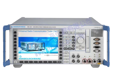
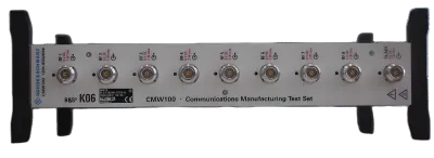
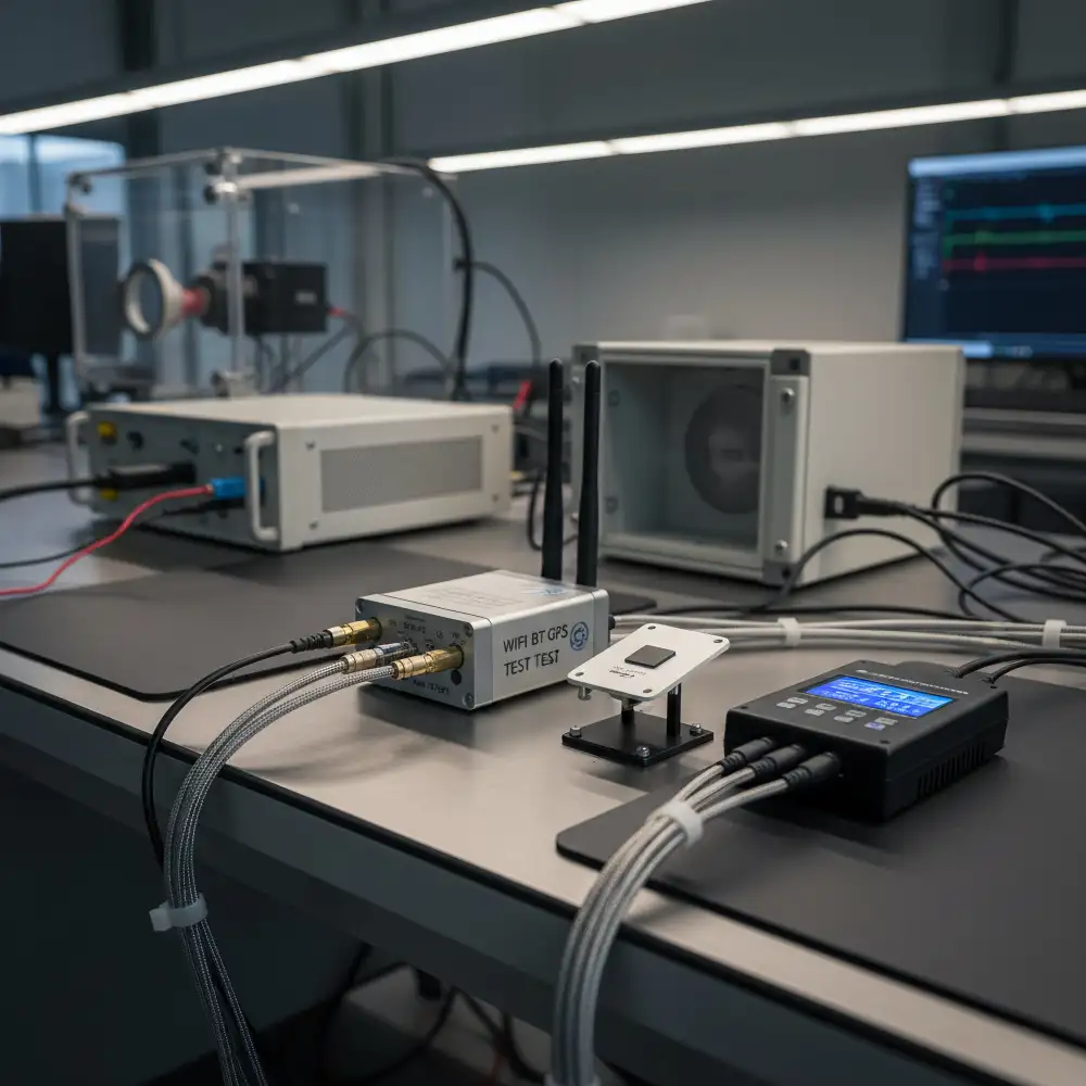
Common failures arise from overlapping protocol wakeups causing retransmissions and current spikes. Workflow: (1) plan channel and duty scheduling; (2) capture concurrent WiFi/Bluetooth/GNSS with the WIFI BT GPS test Set; (3) timestamp power rail events; (4) isolate congestion or retry bursts; (5) optimize power states and TX levels. Metrics: retransmission rate <3% in active window, wake current staircase shape, RSSI stability. Correlating with Section 3 enables quantitative energy savings. A Signal Generator can inject controlled interference to stress margins and reduce later EMI pre-compliance testing iterations.
RF Spectrum Intelligence
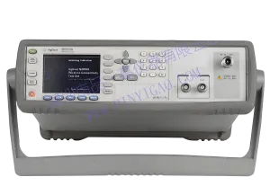
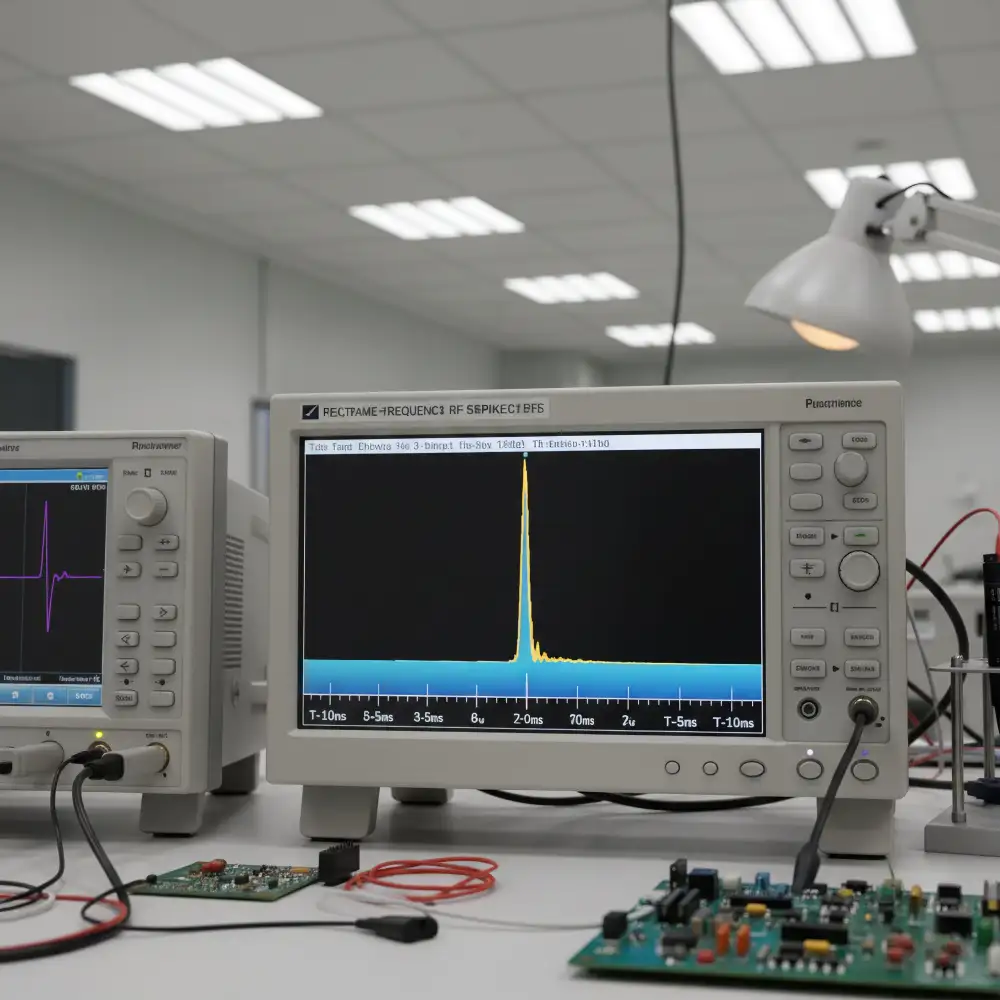
Transient uplink bursts or fast charge negotiation harmonics can mask intermittent link jitter. Workflow: (1) wide real-time capture on Spectrum Analyzer; (2) deep demodulation on Signal Analyzer; (3) correlate timestamps with Section 3 power events; (4) localize interference source; (5) apply filtering or scheduling separation. Metrics: transient spurious < -50 dBc, noise floor rise <3 dB. If emission coincides with a power pulse, revisit protocol timing. Mitigation reduces retransmissions and overall energy consumption while preparing cleaner EMI pre-compliance testing baselines.
Power & Energy Optimization
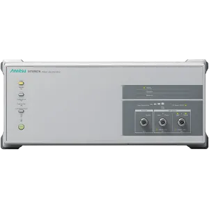
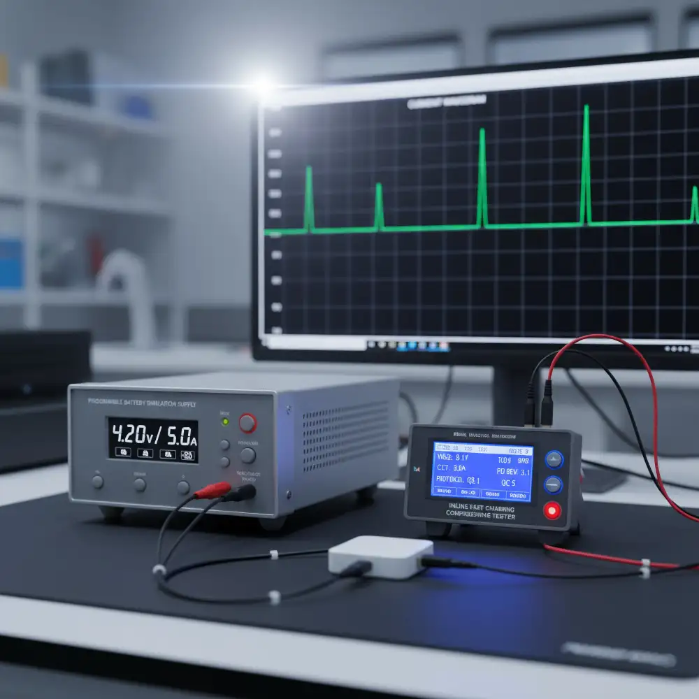
Multi-decade dynamic current plus charging negotiation leads to misestimated capacity if unprofiled. Workflow: (1) Battery Simulating Power Supplies perform battery simulation internal resistance & OCV steps; (2) Fast Charging Comprehensive Tester captures USB PD/PPS/QC exchanges; (3) power meter and Multimeter validate transient accuracy; (4) analyze dynamic power profile; (5) tune current limits and sleep thresholds. Metrics: negotiation time, overshoot <50 mV, average sleep current <2 µA. Correlation with Section 2 transient emissions isolates negotiation-induced spikes, allowing firmware timing or filter adjustments.
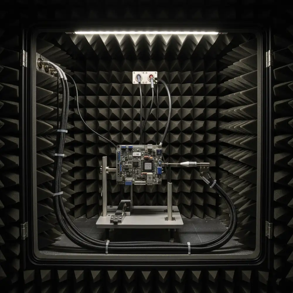
Shielded & Controlled Environments
External uncertainty obscures intrinsic emissions and receive sensitivity shifts. Workflow: (1) validate Shielding Box attenuation; (2) implement filtered feedthrough and grounding; (3) inject calibrated reference signal; (4) run combined protocol/power/spectrum tests; (5) baseline report feeding Section 7 compliance planning. Metrics: shielding effectiveness >80 dB at 2.4 GHz, VSWR <1.3. Persistent internal peaks indicate layout or filtering changes needed. Early isolation reduces certification iteration count and accelerates risk mitigation.
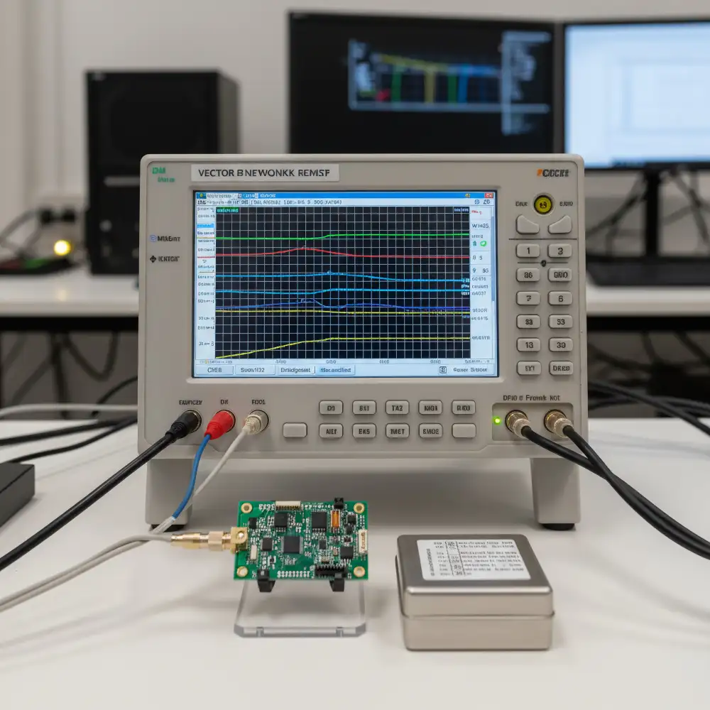
Component & Interface Characterization
Imperfect matching drives PA compression and degraded sensitivity. Workflow: (1) calibrate Network Analyzer (SOLT); (2) measure S-parameters S11/S21; (3) verify linearity with Signal Generator plus power meter; (4) tune matching network; (5) re-evaluate link budget. Metrics: S11 < -10 dB, link margin >6 dB, group delay variation <2 ns. If S21 ripple aligns with spurious from Section 2, adjust filter order or placement. Captured data populates the scalable repository enabling future MIMO expansion.
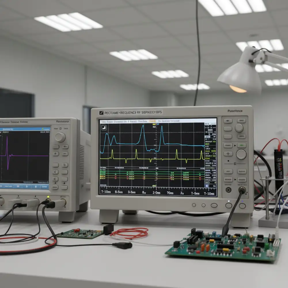
High-Speed Signal & Event Debug
Low duty cycle wake events and protocol edge jitter are easily misinterpreted. Workflow: (1) Oscilloscope multi-domain triggering (power threshold + RF trigger output); (2) capture current waveform and serial bus; (3) align protocol timestamps; (4) localize abnormal latency; (5) refine firmware timing and rail filtering. Metrics: rise time, jitter <500 ps, transient recovery <200 µs. Cross-check reduced pulse area with Section 3 energy profile. Precision correlation decreases root-cause time and supports downstream reliability assessments.
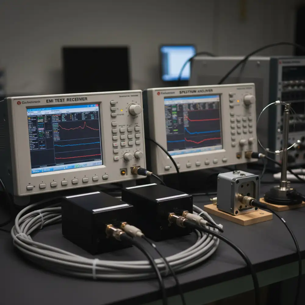
Compliance & Pre-Scan Strategy
Skipping early EMI pre-compliance testing raises formal certification failure probability. Workflow: (1) move from Shielding Box baseline (Section 4) to open pre-scan bench; (2) peak/quasi-peak/average scans; (3) compare Spectrum Analyzer with EMI Test Receiver; (4) prioritize mitigation actions; (5) verify reductions. Metrics: margin ≥3 dBµV at critical bands, ripple-correlated emission reduction >5 dB. Spikes coincident with charging negotiation (Section 3) may require firmware pacing or localized shielding. Structured pre-scan loops can reduce costly late redesign cycles.
Future-Ready Extensibility
Fragmented data limits AI anomaly detection and channel emulation readiness. Strategy: (1) unify time base across RF, power, protocol; (2) central data lake; (3) feature extraction (harmonics, power steps, S-parameters drift); (4) AI clustering of anomalies; (5) digital twin replay for new band or MIMO evolution. Metrics: query latency, anomaly recall. Leveraging Sections 1 and 3 synchronized logs accelerates migration to emerging standards. Modular expansion allows adding Signal Generator channels and automated calibration to support predictive maintenance and scalable test architecture.
Product Recommendations
View All